Abstract
To meet the requirements of gas-liquid-solid three-phase separation in wellhead natural gas recovery and processing systems, the basic structure of a gas-liquid-solid three-phase cyclone separator was determined. Based on Fluent numerical simulation combined with the Mixture multiphase flow model and RNG k-ε turbulence model, the influence of different operating parameters on the internal flow field and separation performance of the separator was investigated. An orthogonal experimental design was employed to optimize multiple operating parameters, including inlet flow rate, sand volume fraction, and water volume fraction, thereby revealing the primary and secondary influence patterns of these parameters on separation efficiency. The results indicate that the primary factor affecting sand separation efficiency is the inlet flow rate, followed by the sand volume fraction and water volume fraction. Under the optimal operating parameters (an inlet flow rate of 5.65L/s, a sand volume fraction of 2%, and a water volume fraction of 4%), the separation efficiencies of sand and water reach 98.89% and 20.85% respectively, showing a significant improvement compared with pre-optimization levels. These findings provide theoretical guidance for the engineering design and efficient operation of gas-liquid-solid cyclone separation devices.
Keywords
Orthogonal test Gas-liquid-solid three-phase Cyclone separator Operating parameters Numerical simulation Separation efficiency
1. Introduction
Cyclone separators, characterized by their simple structure, absence of moving parts, low operation and maintenance costs, and excellent operational performance, can function properly under high-temperature and high-pressure environments. They have become virtually the only gas-solid separation equipment capable of long-term, large-scale application in industrial production [1][3]. Through continuous research over the years, the separation performance of cyclone separators has reached a relatively high level.
Many experts and scholars globally have conducted in-depth research on cyclone separators. Ma Lingkai et al. [4] demonstrated via numerical simulation that the inlet structural design directly affects the symmetry of the internal flow field in a cyclone separator; unreasonable inlet conditions can exacerbate the internal flow "tail-wagging" phenomenon and degrade separation performance. Wang Haokai et al. [5] designed a counter-current double-helix-blade gas-liquid-solid multiphase swirl separator for natural gas hydrate extraction conditions, established a turbulent mathematical model for gas-liquid-solid multiphase separation, and revealed the patterns of how structural parameters—such as pitch, the number of helical blades, and the number of helical turns on separation performance. They found that when the inlet velocity reached 3.0 m/s, the separation efficiencies for the gas and solid phases increased to 98.6% and 83.2%, respectively.
Qian Yubao et al. [6] used numerical simulation methods to calculate the flow field of the separator, studying the distribution of the gas-phase velocity field and pressure field. Li Yanxi et al. [7] designed a new type of volute multi-channel cyclone separator based on spiral theory. Wang et al. [8] carried out systematic CFD numerical simulations on the insertion pipe structure below the overflow pipe of the cyclone separator, comparatively analyzed the influence laws of diverging and converging insertion pipes on the internal swirling flow field and separation efficiency, and accurately captured the strong rotational flow characteristics using the Reynolds stress turbulence model, providing a research paradigm for the structural optimization and numerical method selection of cyclone separators. Fatahi et al. [9] used the CFD-DPM method combined with the Taguchi experimental design to study the effects of operating parameters such as inlet velocity, inlet temperature, and particle mass flow rate on the performance of a square cyclone separator, quantified the contribution of each parameter to separation efficiency through analysis of variance, and found that inlet velocity has the most significant impact on performance. Utikar R et al. [10] used CFD to perform simulation calculations on the cyclone separator, analyzing the characteristics of the pressure and velocity fields. Avci A et al. [11] theoretically analyzed the pressure losses in cyclone separators and established a new equation capable of predicting pressure loss. Elsayed K et al. [12] used the Reynolds Stress Turbulence Model (RSM) to compute five cyclone separators, investigating the effect of cyclone inlet dimensions on performance and flow field patterns. Li Teng et al. [13] conducted numerical simulations on the distribution of the gas-phase flow field and the trajectory of droplet particles, examining the influence laws of droplet size and inlet velocity on separation efficiency. Lu Qiuyu et al. [14] utilized orthogonal tests combined with computational fluid dynamics software to optimize structural parameters such as the length of the cylindrical section of the gas-liquid cyclonic cavity, the cone angle, and the insertion depth of the exhaust pipe, obtaining the optimal parameter combination through intuitive analysis and analysis of variance, increasing separation efficiency to over 95%, which was verified by indoor experiments. Zhang Jun et al. [15] took overflow port diameter, underflow port diameter, cone angle, overflow pipe insertion depth, and cylindrical section length as design variables, constructed an L₁₆(4⁵) parameterized orthogonal optimization experimental model, and determined the optimal combination parameters through range analysis. After optimization, the pressure drop was reduced by 9842 Pa, and separation efficiency increased by 12%.Wei Qing et al. [16] obtained a method for rationally distributing the internal energy of the cyclone separator and the variation range of the inlet gas velocity by analyzing the changes of the internal flow field with inlet shape, structural dimensions, and operating conditions, and established a calculation model for maximum-efficiency gas velocity. Zhang Lei et al. [17] used the Eulerian multiphase flow model and the Reynolds stress model to study the influence laws of different inlet velocities and gas volume fractions on the gas-phase volume fraction distribution, pressure field, and velocity field in a gas-liquid cyclone separator.
In summary, the research and analysis of cyclone separators have gradually become comprehensive in both numerical simulation and structural optimization; however, with continuous industrial development, separators with higher precision and separation performance are required to adapt to complex operating conditions [18]. Scholars at home and abroad have conducted extensive research on the structural parameters of cyclone separators and the inlet components of horizontal separators [19], but two shortcomings remain: First, most studies focus on gas-solid or gas-liquid two-phase systems, with less research on the gas-liquid-solid three-phase separation of wellhead natural gas; Second, existing optimizations mostly concentrate on structural dimensions, with insufficient research on the multi-factor coupled optimization of operating parameters such as inlet flow rate, sand content, and water content. Therefore, this paper comparatively analyzes the influence of different operating parameters on the internal flow field and separation efficiency of the separator. Finally, through orthogonal experiments, the influence laws of complex parameters on the performance of the gas-liquid-solid three-phase separator are analyzed to obtain the optimal operating parameters for the gas-liquid-solid three-phase separation device.
2. Structure and Working Principle of Cyclone Separator
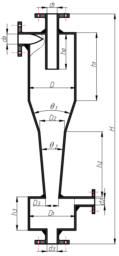
The main structure of the cyclone separator is primarily divided into the inlet and outlet section, the cyclonic section, and the settling section, among which the inlet and outlet section includes the inlet, overflow port, liquid discharge port, and sand discharge port; The cyclonic section comprises the cylindrical section, large conical section, and small conical section; the settling section is mainly the sand storage tank. Figure 1 shows the structural schematic of the cyclone separator.
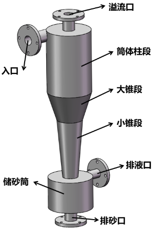
| Structure Name | Dimensions |
| Diameter of the cylinder section | 190mm |
| Inlet pipe diameter | 32mm |
| Overflow pipe diameter | 38mm |
| Overflow pipe insertion depth | 165mm |
| Sand storage tank inlet diameter | 48mm |
| Angle of the large cone section | 24° |
| Angle of the small taper section | 2° |
The working principle of the cyclone separator utilizes strong centrifugal force to achieve the separation of mixtures under high-speed rotation. For example, in a classic static hydrocyclone, external pressure is used to push the material mixture into the interior of the cyclone at a high velocity. Because the mixture enters tangentially from the cyclone, it is prompted to undergo rotational motion along the cylinder wall—a motion generally referred to as external swirling flow or external vortex [20]. As shown in Figure 2.
3. Establishment of Gas-Liquid-Solid Three-Phase Flow Model
Computational Fluid Dynamics (CFD) mainly involves discretizing the relevant differential equations of physical models and using computers to conduct quantitative analysis and prediction of fluid-related physical characteristics; its accuracy is affected by the precision of equation discretization and computer technology[21]. To study the relationship between the operating parameters of the cyclone and its separation efficiency, since the internal flow field conditions are not easily observable, a more detailed analysis of the flow field requires the use of CFD analysis methods.
Research indicates that when used for three-phase separation numerical simulation calculations, the final error between the Fluent software simulation results and the experimental results is within 10%, which is an acceptable range. The simulation results are considered basically consistent with actual values, and the calculation results of the flow and pressure fields conform to reality. Therefore, the accuracy of the software model meets the requirements, and Fluent software can be used for corresponding analysis, design, and optimization.
3.1 Basic Equations of Fluid Mechanics
Calculating the flow field pressure of the cyclone is primarily achieved by solving the continuity equation and the Navier-Stokes (N-S) equations:
If the fluid is considered a Newtonian fluid, the relationship between its shear stress and velocity is (equation in the x-direction only):
For multiphase flow problems, a species conservation equation must also be solved (in the two-component case):
For calculating the above equations, Fluent's calculation process adopts the finite volume method for discretization. The finite volume method is mainly advantageous for maintaining good specific physical meanings during the discretization process; physical quantities in the post-discretization equations require corresponding interpolation and finite-difference approximate calculations. After establishing the equations, linear systems can be solved via Gaussian elimination or the Gauss-Seidel iterative method, while nonlinear systems can be solved via the Newton-Raphson method [22].
3.2 Turbulence Model
Due to the inherent complexity of turbulent flow, there is currently no universal turbulence model applicable to all flow conditions; therefore, it is essential to select an appropriate model based on the specific subject of study, as this is key to ensuring the accuracy of numerical simulation results. Relevant literature indicates that turbulence models suitable for separator simulation include improved k-ε models and the RSM model. Among them, the k-ε model is proposed based on the eddy-viscosity assumption suggested by Boussinesq, introducing the concepts of turbulent kinetic energy and turbulent kinetic energy dissipation during the turbulence process, with the following assumption between Reynolds stress and velocity gradient:
Where the turbulent kinetic energy is:
The model k−ε assumes the turbulent dissipation rate is:
For the cyclone separator, the RNG k-ε model should be adopted, because the Swirl Dominated Flow setting in the RNG k-ε model is frequently used for strong separation analysis. The RNG k-ε model accounts for the influence of vortices on the flow field by adding a condition to the equation, improving accuracy, and is suitable for swirling flows, vortices, and strong streamline curvature. Research shows that this is an ideal model suitable for calculating the internal flow field of centrifugal cyclone separators. Therefore, the RNG k-ε model is employed for the simulation analysis of the cyclone separator.
3.3 Multiphase Flow Model Selection
The VOF model is suitable for two-phase flow conditions featuring clear interfaces that do not mix. However, the separator studied in this paper involves simulating gas, water, and sand, where the gas and water phases will mix; thus, the VOF model is inapplicable. Conversely, the Mixture model is commonly used for settlers and cyclone separators, and existing literature has proven it offers high precision, low cost, and good stability in separator simulation while meeting accuracy requirements. The Lagrangian method is primarily used for trajectory analysis of the discrete phase, suitable for situations where the discrete phase accounts for no more than 10%. Therefore, the Mixture model is adopted to analyze the separator.
4. Numerical Simulation Analysis for Operating Parameter Optimization
4.1 Geometric Model Establishment
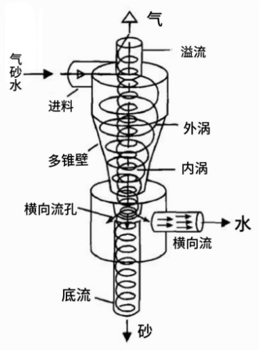
The physical model of the gas-liquid-solid separator is established and imported into Design Modeler within ANSYS Workbench, yielding the geometric model of the cyclone separator as shown in Figure 3.
4.2 Mesh Generation of Cyclone Separator
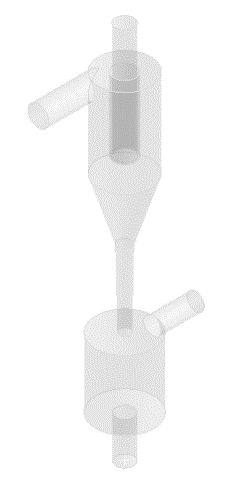
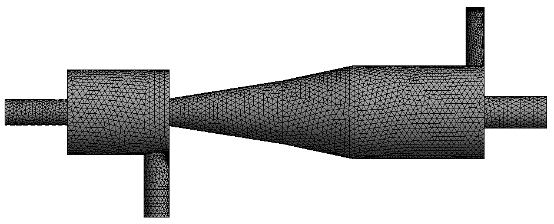
The flow channel model is meshed using the built-in Mesh tool in Workbench, as shown in Figure 4. Extra minute features may be generated when importing external models, which can degrade mesh quality; these minute features can be ignored by setting feature values, such that features smaller than or equal to the designated feature value are automatically removed. Because the internal separation components of the separator have complex structures, featuring internal holes, corners, and narrow regions, curvature capturing and proximity capturing are set to "Yes" to improve mesh quality. This automatically refines the mesh in areas with curvature changes, narrow regions, and thin walls, thereby enhancing overall mesh quality. The generated mesh has 32,525 nodes and 163,437 elements, with a mesh quality of 0.88.
4.3 Boundary Condition Setup
(1)Fluid Properties
The gas-liquid-solid three-phase separator is equipment used to process mixtures containing gas, liquid, and solid particles Separator design pressure: 22 MPa; design temperature: 80℃; working temperature: -19~40℃; safety valve pop-off pressure: 21.5 MPa; working medium: oil, water, and natural gas (non-sour natural gas); working pressure: 3-20 MPa; equipment processing capacity indices: natural gas: 5×10⁴ m³/d, liquid: 50 m³/d.
(2)Boundary Conditions and Solution Control
Boundary conditions in FLUENT are mainly divided into inlet/outlet boundaries, other external boundaries, and internal boundaries. Selecting appropriate boundary conditions is extremely important for stability during the calculation process, as different flow field environments necessitate different types of boundary conditions. For this computational model where droplets have only a single inlet and outlet within the flow field, the most stable boundary condition types are set as velocity-inlet and pressure-outlet. The specific boundary condition selections are as follows:
①Inlet boundary
Set as velocity-inlet. Calculated using gas density, gas flow rate, and inlet cross-sectional area, the inlet velocities under various operating conditions are 3.24 m/s, 4.5 m/s, 5.76 m/s, and 7.02 m/s.
②Outlet boundary
Set as pressure-outlet at 10 MPa, and defined as an escape boundary; when a particle travels to the pressure-outlet boundary, it is considered not to have been separated.
③Wall
The model boundary is set to the 'wall' boundary condition, acting as a no-slip wall.
4.4 Numerical Simulation Analysis
(1)Flow Field Analysis
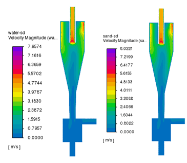
Analyzing the velocity contour in Figure 5 reveals that after the gas mixture enters the gas-liquid-solid separator from the inlet, there is a large velocity variation in the inlet area, and the gas separation from the top outlet is quite obvious. The liquid and sand phases are separated in the large conical section due to the strong centrifugal force of the separator.
(2)Separation Efficiency Analysis
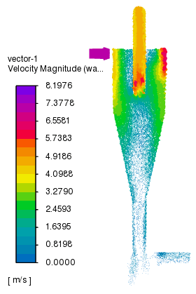
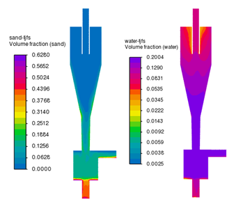
Figure 7 displays the contour map of the volume fraction of the liquid phase relative to the total, monitored during the simulation using the Mixture model. From this, we can observe that the sand particles in the mixed fluid are eventually separated out and deposited at the bottom of the separator. By monitoring the mass flow rate at the inlet alongside the mass flow rate at the outlet, the separation efficiency of each phase is obtained based on the defined calculation method for gas-liquid-solid separation efficiency:
5. Optimization of Operating Parameters
5.1 Orthogonal Experimental Design of Operating Parameters
Once the optimal structure of the cyclone separator is determined, to explore the influence of different operating parameters on the separation efficiency and determine the optimal operating parameters, it is necessary to conduct an optimized design on various operating parameters, thereby improving the separator's efficiency. Based on the orthogonal experimental method, the parameters optimized in this paper include: inlet flow rate, sand volume fraction, and water volume fraction. There is a total of 3 factors, with each factor taking 4 levels. A total of 43 simulations are required. Since an excessive number of simulations wastes resources, adopting an orthogonal table for simulation design is considered to reduce the simulation count while ensuring simulation reliability[23].
Table 2 shows the optimization table for the cyclone separator's operating parameters. SPSS software was used to generate an orthogonal test table for the factor levels. The generated orthogonal table is shown in Table 3, requiring a total of 16 simulations.
| Optimization Parameters | Optimize Parameter Values | |||
| Inlet Flow(L/s) | 2.61 | 3.62 | 4.63 | 5.65 |
| Volume fraction of sand particles(%) | 2 | 3 | 4 | 5 |
| Volume fraction of water(%) | 4 | 6 | 8 | 10 |
| Number | Inlet Flow (L/s) | Volume fraction of sand particles (%) | Volume fraction of water (%) |
| 1 | 2.61 | 2 | 4 |
| 2 | 2.61 | 3 | 6 |
| 3 | 2.61 | 4 | 8 |
| 4 | 2.61 | 5 | 10 |
| 5 | 3.62 | 2 | 6 |
| 6 | 3.62 | 3 | 4 |
| 7 | 3.62 | 4 | 10 |
| 8 | 3.62 | 5 | 8 |
| 9 | 4.63 | 2 | 8 |
| 10 | 4.63 | 3 | 10 |
| 11 | 4.63 | 4 | 4 |
| 12 | 4.63 | 5 | 6 |
| 13 | 5.65 | 2 | 10 |
| 14 | 5.65 | 3 | 8 |
| 15 | 5.65 | 4 | 6 |
| 16 | 5.65 | 5 | 4 |
5.2 Simulation Result Analysis of Orthogonal Experiment on Operating Parameters
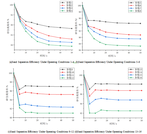
Adopting the orthogonal experimental method to optimize operating parameters aims to determine under which working conditions the sand separation efficiency peaks, providing a theoretical basis for subsequent practical operations. During simulation, the sand and water flowing out of the cyclone separator's overflow pipe were monitored. By calculating the mass flow rate of sand and water entering the inlet pipe and the mass flow rate of sand and water exiting the overflow pipe, the separation efficiencies of sand and water were derived. Simultaneously, to explore the impact of the 16 sets of operating parameters on the separator's efficiency, the temporal variations in sand and water separation efficiencies under these 16 sets of parameters were plotted separately, as shown in Figures 8 and 9.
By observing the time-varying trend of sand separation efficiency under the 16 sets of cyclone separator parameters, it is evident that sand separation efficiency under all operating parameters basically reaches a stable state at around 40 seconds, and different operating parameters have a substantial impact on sand separation efficiency. Furthermore, a larger inlet flow rate results in smaller fluctuations in the cyclone separator's sand separation efficiency and yields a higher overall separation efficiency for sand. Therefore, when determining the inlet flow rate for the cyclone separator later, a relatively large inlet flow rate should be preferentially selected. As can be seen from Figure 8a: when the inlet flow rate remains constant, simultaneous increases in the sand volume fraction and water volume fraction will lead to a decrease in sand separation efficiency. In practical production, measures should be taken to avoid the simultaneous increase of sand and water volume fractions. Observing the results for operating conditions 1, 5, 9, and 13 shows that: when the sand volume fraction remains constant, simultaneous increases in both the inlet flow rate and water volume fraction will improve the sand separation efficiency.
By observing the time-varying trend of sand separation efficiency under the 16 sets of parameters, it can be seen that: the water separation efficiency across all parameters basically reaches a steady state at around 20 seconds, and different operating parameters have little effect on water separation efficiency. This structure of the cyclone separator has a low separation efficiency for water, making it unsuitable for operating conditions with stringent requirements for water separation efficiency.
| Parameter Number | Inlet Flow (L/s) | Volume fraction of sand particles (%) | Volume fraction of water (%) | Sand Particle Separation Efficiency(%) | Water-separation efficiency(%) |
| 1 | 2.61 | 2 | 4 | 88.19 | 16.07 |
| 2 | 2.61 | 3 | 6 | 82.96 | 13.29 |
| 3 | 2.61 | 4 | 8 | 81.28 | 11.16 |
| 4 | 2.61 | 5 | 10 | 79.36 | 9.43 |
| 5 | 3.62 | 2 | 6 | 94.37 | 17.64 |
| 6 | 3.62 | 3 | 4 | 90.74 | 15.29 |
| 7 | 3.62 | 4 | 10 | 89.52 | 12.21 |
| 8 | 3.62 | 5 | 8 | 87.25 | 10.61 |
| 9 | 4.63 | 2 | 8 | 96.98 | 19.00 |
| 10 | 4.63 | 3 | 10 | 95.18 | 15.69 |
| 11 | 4.63 | 4 | 4 | 92.34 | 14.21 |
| 12 | 4.63 | 5 | 6 | 90.9 | 11.69 |
| 13 | 5.65 | 2 | 10 | 98.12 | 19.88 |
| 14 | 5.65 | 3 | 8 | 96.75 | 17.32 |
| 15 | 5.65 | 4 | 6 | 94.77 | 14.97 |
| 16 | 5.65 | 5 | 4 | 92.49 | 12.56 |
As known from the results in the table, when the operating parameters correspond to the 13th group, the separation efficiencies for sand and water are the highest among the 16 sets of tests, peaking at 98.12% and 19.88%, respectively. When ignoring the impact of interactions among various operating factors on separation performance, the range analysis method can be utilized to analyze the simulation results of the orthogonal test operating parameters, thereby preliminarily obtaining the optimal parameter combination.
Taking the level of sand separation efficiency as the criteria for judging separator performance, the sand separation efficiencies under the 16 sets of different operating parameters were individually processed. Table 5 displays the results of the range analysis for the operating parameters.
| Item | Inlet Flow (L/s) | Volume fraction of sand particles (%) | Volume fraction of water (%) |
| K1 | 331.79 | 377.66 | 363.76 |
| K2 | 361.88 | 365.63 | 363.00 |
| K3 | 375.40 | 357.91 | 362.26 |
| K4 | 382.13 | 350.00 | 362.18 |
| k1 | 82.95 | 94.42 | 90.94 |
| k2 | 90.47 | 91.41 | 90.75 |
| k3 | 93.85 | 89.48 | 90.57 |
| k4 | 95.53 | 87.50 | 90.55 |
| R | 12.59 | 6.92 | 0.39 |
| Optimal Levels of Factors | 4 | 1 | 1 |
| Order of Importance of Factors | Inlet flow rate > Volume fraction of sand particles > Volume fraction of water | ||
| Theoretically Optimal Portfolio | Inlet Flow 5.65L/s | Volume fraction of sand particles 2% | Volume fraction of water 4% |
From the range analysis results, the following preliminary conclusions can be drawn: when not considering the effect of factor interactions on separation performance (i.e., looking only at the isolated impact of a single factor on sand separation efficiency), the factor with the greatest impact is the inlet flow rate. The sand volume fraction has a certain degree of influence on sand separation efficiency. The water volume fraction has virtually no effect on sand separation efficiency.
Selecting an inlet flow rate of 5.65 L/s, a sand volume fraction of 2%, and a water volume fraction of 4% constitutes the optimal operating parameters to maximize sand separation efficiency. Consequently, the theoretical optimal operating parameters of the cyclone separator are preliminarily determined, as shown in Table 6.
| Optimization Parameters | Value |
| Inlet Flow (L/s) | 5.65 |
| Volume fraction of sand particles (%) | 2 |
| Volume fraction of water (%) | 4 |
Based on the optimal operating parameters in Table 6, re-simulation calculations yield a sand separation efficiency of 98.89% and a water separation efficiency of 20.85%. The sand separation efficiency reaches its maximum under these operating parameters.
6. Conclusions
(1)When the influence of interactions among various factors on the separation performance of the cyclone separator is excluded, the factor with the greatest impact on sand separation efficiency is the inlet flow rate. The effect of the water volume fraction on the sand phase separation efficiency is negligible.
(2)At a constant inlet flow rate, a simultaneous increase in both the sand volume fraction and the water volume fraction will lead to a decrease in sand separation efficiency.
(3)The research results demonstrate that the maximum separation efficiency for sand is 98.89%, and 20.85% for water. Post-optimization, the sand separation efficiency increased by 19.53%, and the water separation efficiency increased by 11.43%. This improves the separation performance of the cyclone separator to a certain extent. This research holds guiding significance for the optimal design of cyclone separators.
References
- Lian Z H, An N, Zhao C Y, et al. Structural optimization design of downhole gas-liquid separator based on orthogonal test[J]. China Petroleum Machinery, 2025, 53(9): 96-103. DOI ↗ Google Scholar ↗
- Zeng Y, Chen M, Wei K, et al. Study on structural parameter optimization of built-in guide vanes in cyclone separator[J/OL]. China Petroleum Machinery, 2024: 1-13[2024-07-01]. DOI ↗ Google Scholar ↗
- Wang M Y. Research on key technologies of wellhead natural gas recovery and processing system[D]. Jingzhou: Yangtze University, 2025. DOI: . DOI ↗ Google Scholar ↗
- Ma L K, Liu X H. Numerical simulation study on velocity flow field and separation efficiency of double-inlet cyclone separator[J]. Journal of Yangtze University (Natural Science Edition), 2024, 21(2): 85-92. DOI ↗ Google Scholar ↗
- Wang H K, Liu X F, Li Q P, et al. Gas-liquid-solid multiphase cyclone separation characteristics of counter-flow double helical blade[J]. China Petroleum Machinery, 2024, 52(3): 88-97. Google Scholar ↗
- Qian Y B, Guo X T, Qiu T H. Numerical simulation study on gas-solid flow characteristics of cyclone separator[J]. Light Metals, 2024(1): 1-6. Google Scholar ↗
- Li Y X, Wang Y C, Xie X D, et al. Structure optimization and separation characteristics of volute-type multi-channel gas-liquid cyclone separator[J/OL]. CIESC Journal, 2024: 1-18[2024-07-01]. DOI ↗ Google Scholar ↗
- Wang M, Feng D. CFD investigation on the performance of cyclone separators with divergent or convergent insertion pipes[J]. Processes, 2023, 11(7): 2061. DOI ↗ Google Scholar ↗
- Fatahi H, Fatahi E, Erfani R. Square cyclone separator: performance analysis optimization and operating condition variations using CFD-DPM and Taguchi method[J]. Powder Technology, 2023, 426: 118689. DOI ↗ Google Scholar ↗
- Utikar R, Darmawan N, Tade M, et al. Hydrodynamic simulation of cyclone separators[M]// InTech. Computational Fluid Dynamics. Rijeka: InTech, 2010: 215-236. Google Scholar ↗
- Avci A, Karagoz I. Theoretical investigation of pressure losses in cyclone separators[J]. International Communications in Heat and Mass Transfer, 2001, 28(1): 87-96. Google Scholar ↗
- Elsayed K, Lacor C. The effect of cyclone inlet dimensions on the flow pattern and performance[J]. Applied Mathematical Modelling, 2011, 35(4): 1952-1968. Google Scholar ↗
- Li T, Sun Z Q, Wang C L, et al. Numerical simulation study on micro double-volute gas-liquid cyclone separator[J]. China Petroleum Machinery, 2022, 50(6): 78-85. Google Scholar ↗
- Lu Q Y, Liu H, Song J. Optimization of structural parameters of integrated degassing and deoiling hydrocyclone[J]. Mechanical Science and Technology for Aerospace Engineering, 2021, 40(5): 737-743. Google Scholar ↗
- Zhang J, Liu H W, Cheng G F, et al. Flow field characteristics and structure optimization of liquid-solid two-phase hydrocyclone[J]. Journal of Shanghai Ocean University, 2024, 33(4): 895-905. Google Scholar ↗
- Wei Q, Sun G G, Yang J X. A model for prediction of maximum-efficiency inlet velocity in a gas-solid cyclone separator[J]. Chemical Engineering Science, 2019, 204: 287-297. Google Scholar ↗
- Zhang L. Study on flow field characteristics and separation performance of gas-liquid cyclone separator[D]. Daqing: Northeast Petroleum University, 2023. Google Scholar ↗
- Wang M Y, Sun Q L, Feng D, et al. Design and analysis of gas-liquid separator for skid-mounted wellhead gas recovery system[J]. China Petroleum Machinery, 2023, 51(10): 113-119. Google Scholar ↗
- Wen Y L, Feng D, Xiong L C, et al. Inlet structure optimization and separation efficiency of horizontal gas-liquid separator[J]. Science Technology and Engineering, 2026, 26(6): 2385-2392. DOI ↗ Google Scholar ↗
- Chen Z. Design and simulation study of wellhead oil-water-sand hydrocyclone[D]. Jingzhou: Yangtze University, 2021. Google Scholar ↗
- Fan H H. Optimal design of hydrocyclone based on CFD simulation and multi-objective coupled preference decision optimization method[D]. Ganzhou: Jiangxi University of Science and Technology, 2023. Google Scholar ↗
- Qi X Y. Study on mixing and droplet migration characteristics of oil-water two-phase flow[D]. Beijing: China University of Petroleum (Beijing), 2023. Google Scholar ↗
- Chen L Q, Li S X, Wang J Y. Parameter optimization of rectifying component in oil-water separator based on orthogonal test[J]. China Measurement & Test, 2023, 49(6): 151-156. Google Scholar ↗